Views: 8793 Author: James Wu Publish Time: 2020-06-06 Origin: Site
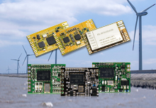
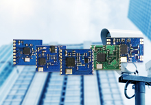
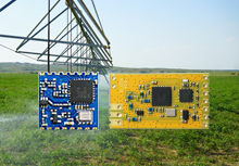
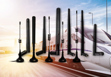
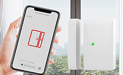
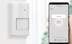
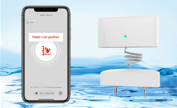
As an indispensable part of wireless LAN applications, antennas will have different requirements in different applications. The antenna is equipped with a full range of antennas for terminal equipment, providing a variety of installation modes to achieve simple and fast installation, and can cover a variety of outdoor or indoor application scenarios.
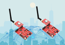
LoRa is one of the LPWAN communication technologies, and it is an ultra-long-distance wireless transmission scheme based on spread spectrum technology adopted and promoted by the US Semtech company. This solution changes the previous compromise between transmission distance and power consumption, providing users with a simple system that can achieve long distance, long battery life, and large capacity, and then expand the sensor network.
LoRa technology compared with other wireless technologies:
At present, LoRa mainly operates in free frequency bands around the world, including 433, 868, and 915 MHz.
LoRa technology has the characteristics of long distance, low power consumption (long battery life), multiple nodes, and low cost.
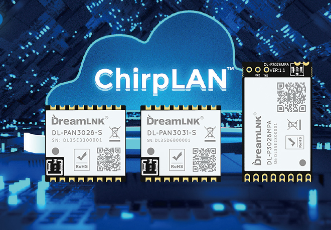
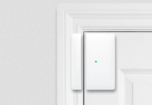
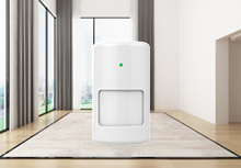
The LoRa network is mainly composed of a terminal (with built-in LoRa module), a gateway (or base station), a server, and a cloud. Application data can be transmitted in both directions.
With the continuous fever of LoRa technology in the industry, coupled with its unique and superior transmission performance, the group using LoRa technology is exploding. Because a large number of groups are the first contact with RF technology such as LoRa, they are in the process of making products. In general, we often encounter difficult RF circuit design problems. In fact, as long as you master a few key points, you can basically play the performance of LoRa.
Point one, matching circuit design
Point two, microstrip line routing rules
Point three, LoRa module stamp hole antenna interface
Point four, PCB floor requirements
We have encountered many situations in which users use our modules on products, product programs use the same configuration parameters as our evaluation boards, and use the antennas on our evaluation boards, but the communication effect is significantly better than our evaluation boards. Much worse. The three key parameters related to the communication distance are the transmission power, the receiving sensitivity and the antenna. The first two parameters were tested when our module was shipped from the manufacturer. The unqualified products are treated as waste products, while the antenna is It varies according to the user's design. The distance that affects communication is mainly the parameter of the antenna. The other two parameters will hardly change greatly due to the difference of the user's board. In the air, the electromagnetic wave with a frequency of 470MHz has a wavelength of 63CM. If a standard half-wave dipole antenna is designed, this antenna will be at least half a wavelength, or 31.5CM. In practical applications, most products do not reserve such a large space for antenna design, so spring antennas are generally used. When using this spring antenna, the antenna is connected to different boards, and its performance parameters are different. This is because in this type of antenna, the spring is only a part of the entire antenna, and the other part is the ground on the circuit board. Therefore, when laying the circuit, you must pay attention to it. The general principle is: First, make the antenna vertical Circuit board installation, the second is to make the copper block of the floor as large and continuous as possible, and rely on dense vias to make the front and back of the floor continuous.
Point five, antenna installation specifications
After all the hardware parameters are adjusted, the installation of the antenna is also a key step. The antenna radiation is directional, not equal energy is radiated in each direction. Just like we talk, some directions hear strong sounds, some directions weak. When installing an antenna, you need to align the antenna with the strongest radiation direction to the receiving antenna. The receiving antenna can obtain the strongest received signal. To do this, you must first know the radiation direction of the antenna.
In the absence of a professional antenna testing laboratory such as a dark room, how to test the radiation direction of the antenna? After finalizing the product, we can let it continuously send data and use a spectrum analyzer to test the signal strength at a certain distance from the product. Rotate the product under test and record the signal strength in all directions, so that you can draw the antenna radiation pattern of the product.