|


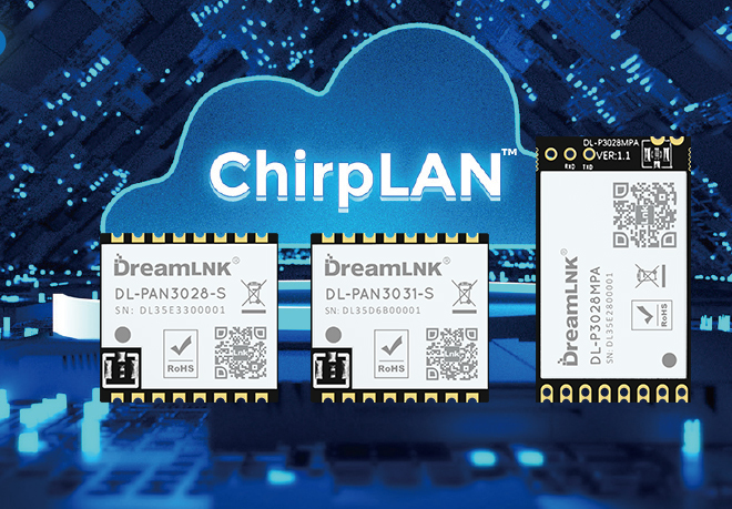
DreamLNK
DL-RXC6A / DL-RXC6B
433/315 MHz
1527 Learning Code
2.8~5.5V
-112dBm
300m
28.5*12*6mm
| Quantity: | |
|---|---|
4-Channel Switching Value RF Receive Module with Decoding (learning code) Function
DL-RXC6A / RXC6B is a low cost, small size, high sensitivity wireless receive module, with decoding (learning code) function, and super heterodyne ISM band. It adopts cost-effective wireless data receiving chip and low power consumption single chip, built-in image suppression of RF chip, can support 2.8V-5.5V wide voltage power supply, which performs high receiving sensitivity, as well as good anti-interference performance.
This Wireless ASK receiving module can meet your needs (realize the application) by setting the logic state of T1 and T2, and independently leads out three ports as following: LED code-checking status indication, SW learning code- checking button, and VT public valid signal indication. The LED indicator and SW learning code-checking button can be led to the circuit board or casing of the product, which is convenient for the user to operate.
DL-RXC6B leads out the T1 and T2 setting ends of the A version. The module pins adopt a 2.0mm pitch to reduce the size of the module. It also adopts T-type board double-sided in-line pad design. Its bottom plate uses a slotted in-line method, which the module can be inserted directly on the circuit board and then wave soldering. By this way, it can save the soldering of the black pin and reduce the height of the module to 10mm.
DL-RXC6A / DL-RXC6B are compatible with PT2262 and 1527 encoding. The corresponding decoding and receiving module can also be ODM (customized) according to different remote-control encoding types.
Features
● Frequency range: 315MHz, 433.92MHz (special frequency can be customized)
● Sensitivity: Up to -112 dBm
● Power supply voltage input range: 2.8V-5.5V (recommended working voltage 3.3V or 5.0V)
● Latch and non-latching mode selection: Set T1/ T2 decoding, output latch / unlatching
● It can be used to learn PT2260, 2262, 1527 remote controllers with good rate compatibility
● Encoded data transmission rate 2.5K bps (Manchester encoding)
● OOK modulation mode, can work with PT4450, 115H, 113, R25 (2SK3356) and other transmitting circuits
● Module size 28.5 × 12 × 6mm (A version), 28.5 × 12 × 6mm (B version, T type plate)
Download Center
DL-RXC6A DL-RXC6B Specification V1.0 ![]()
Technical Parameter
| Parameter | Symbol | State | Reference Value Min. Typ. Max. | Unit | |
| Working frequency | Fc | 315,433.92 ,— | MHz | ||
| Modulation Mode | ASK | ||||
| Receiving sensitivity | 50 ohm antenna direct input /1k Kbps | -112 | dBm | ||
| RF Receive bandwidth | 300 | KHz | |||
Data demodulation bandwidth | Demodulation pulse width is 0.2-1ms | 1,2.5,— | K | ||
| System Start-up time | Ton | ms | |||
| Supply Voltage | VDD | 2.8,3.3 or 5.0,5.5 | V | ||
| Working Current | IRC | VDD=3.3V/315M | 3.9 | mA | |
| VDD=3.3V/433M | 6 | mA | |||
| Logic Truth Table | T1 | T2 | State description |
| M Flash mode | High level (floating) | High level (floating) | The two setting ports of T1 and T2 are floating, and no level is connected. |
L Self-locking mode | High level (floating) | Low level (grounding) | D0-D3 i ndependent output latch state, flipping when valid signal detected |
H Interlocking mode | Low level(grounding) | High level(floating) | D0-D3 i nterlock output, the current signal output remains unique |
| Reserved mode | Low level(grounding) | Low level(grounding) | Other function modes can be customized (not used yet) |
Note: To confirm that the setting is valid, the red DK tool board needs to be powered on and reset,every time after setting the T1 and T2 states
Pin Definitions

DL-RXC6A Module interface definition diagram

DL-RXC6B Module interface definition diagram
| Pin | Description |
| VDD | Power supply 2.8-5.5V, it is recommended to use LDO or battery output, Standard voltage 3.3V or 5.0V |
| GND | Module grounding,Reliably grounded and close to the system filter capacitor |
| LED | External code-matching LED indicator, press 2S for code-matching, light on and flashes 3 times quickly means matching succeed, 8S long press until light off to clear the code |
| VT | Common signal terminal, high level output (signal status indication) when valid signal detected |
| T1、T2 | Working mode setting pins, detailed setting refers to the Logic Truth Table: 11, 10, 01 state only, 00 state is not used |
| D0-D3 | D0, D1, D2, and D3 correspond to four key values of 1000, 0100, 0010, and 0001 of the standard remote control respectively |
| ANT | Antenna (Refer to Figure 3 to design the patch cord and signal feed point) |
Description: D0-D3 data output, corresponding to different remote control key values, can output 0000-1111 BCD code.
Size

Typical application
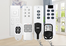
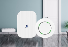
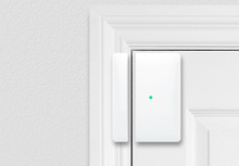
Wireless Data Acquisition, Wireless Data Communication, Wireless Data Monitoring and Transmission, Wireless Sensoring; Wireless Remote Control System; Wireless remote control for electronic consumer products; Wireless Alarm & Security Control System; Wireless Sensor Networking, Automatic Data Collection; Industrial Remote Control, Intelligent Control System, Smart Home, Home Automation, Home Appliance Control, Building and Residential Control, Smart City, Logistics Tracking, RFID (radio frequency identification); Telemetry, Automatic Meter Reading system (Water, Electricity, Gas); Remote control that supports radio frequency (RF) technology
Product Tags
Sub-1Ghz RF Modules, RF Module supplier, ASK RF module, Wireless ASK receiving module, RF Receiver, RF Receive module, ASK Module, RF Receiving module, Switching Control ASK Receiving Module, RF receiver module